
The Warping Square has been partially disassembled for shipping. You will need a #2 Phillips screwdriver (the most common size).
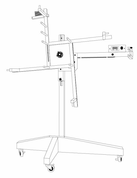
*The base in the image above is different as we recently changed the design.
Parts List
1. Two piece base
2. Stanchion (upright with silver track)
3. Beam Assembly (L shaped slides into track on stanchion)
4. Square Hub Assembly (spins around)
5. Four wooden arms
6. Three casters
7. Parts Bag (four 1.75” screws, nine 1 inch screws, 10 dent reed, reed clip, drive belt if motorized)
8. Foot Pedal (motorized)
9. Power Supply (motorized)
Assembly
1. Unpack contents of box.
2. Begin by assembling the two piece base. Locate the 36 inch base and place it in front of you with the taper facing to the right. Locate the 18 inch base and slide the slot onto the left side of the 36 inch base. Install with two 1.75 inch screws in the holes of the 18 inch base and tighten.
3. Flip the base upside down so that the tapers are facing the ground. Locate the 3 casters and install in the holes provided on the bottom of the bases. The casters are fully locking so you do not need a wrench, just keep them locked. When finished flip the base upright.
4. Locate the stanchion & place stanchion with t-track facing you in the slot on the backside of the 36 inch base. Install with two 1.75 inch screws in the holes on the backside of the stanchion. Tighten screws.
5. Locate beam assembly. Slightly loosen the two knobs on the assembly. DO NOT REMOVE knobs, as the order of the washers on the shaft is VERY important. Align the bolt heads in the back of the beam with the t-track of the stanchion. From the top of the stanchion slide the beam assembly into the track. Tighten bottom (smaller) knob.
6. Locate hub assembly and the three arms. Locate the letters on the back of the 3 arms and match with corresponding letters on the square hub. Install in order (A, B, then C) Secure each arm with three 1 inch screws.
7. Remove the 2 1/4 inch black knob from the beam assembly. Make special note of the orientation and position of the washers. There are two "special" washers called belleville washers that have a cup to them (they are the silver ones sandwiched between black washers). Remove all the parts from the shaft. If your square is motorized install the drive belt along with the hub. The belt is installed by hanging it over the pulley as you slide the hub into place. Leave an inch or so of space in the back so you have space to get the belt over the motor pulley with you fingers. Slide the hub all the way into the shaft. Reinstall washers. Their order is: black washer, silver washer, black washer, silver washer, black washer, spacer with set screw (ensure set screw lines up with slot on shaft), large black knob. Tightening the large black knob increases resistance in the clockwise direction for beaming onto your loom. If you purchased a standard Square assembly is complete, for motorized users keep reading.
8. Locate the foot pedal and power supply. Plug the power supply into the foot pedal and into a wall outlet. Plug foot pedal into the motor. Note that they snap together and that to release them you have to press the button on the metal connector. Turn variable speed knob (the gold knob on the end of the beam) all the way counterclockwise. Ensure that the foot pedal cord and any persons or pets do not interfere with rotating arms. Depress foot pedal and slowly turn the variable speed knob clockwise. Once desired speed is reached release foot pedal. The motor will now attain that rpm each time the pedal is depressed.
Tension adjustment:
The design of the hub allows for precise adjustment of tension for warping onto your sectional beam. There is no need to use an additional tensioning device (aka tension box). To adjust tension rotate center knob clockwise to increase. Set tension before starting to warp onto the beam. Adjustment should then be left for the entire warp to maintain consistency. The Warping Square is designed to freewheel in the opposite direction so there is little resistance when winding onto the square.
Setting warping length
To change warp length the user simply changes the starting position of the yarn. The Warping Square has an inner hub consisting of four pegs. To change the length of the warp the user selects a combination of pegs to feed the yarn through at the beginning of each new warp thread. There is a chart included with the Square for easy reference.
Cross Maker
There is a built in cross maker on the upper arm. The cross maker allows the user to maintain thread order to facilitate pattern creation. The cross maker is not necessary for all warps but is helpful if the user is doing a pattern or warping into a chain for a non-sectional beam. To utilize the cross maker feed the thread through the two pegs from opposite sides every time you drop down from the reed to form a new warp thread. This will create a cross in between the pegs. Before warping onto the beam, tie yarn around the cross to maintain it. Once warping the beam is nearly complete the cross can be slid to leave the desired length of tail. The cross will need to be removed from the reed as it cannot be fed through. Secure with tape to your beam.
Motor Use
The motor is a variable speed design . The speed control knob is located next to the counter on the beaming arm. Rotating knob clockwise increases speed. Speed is adjustable from 5 - 100 rpm. To use motor, plug in the foot pedal and power source assembly to the plug on the back of the Warping Square. Plug the power source into the wall. Check that foot pedal cord will not interfere with the rotation of the Square. Ensure that the variable speed knob is turned all the way counterclockwise (the off position) and depress foot pedal. Slowly turn variable speed knob clockwise until desired speed is reached. Utilize motor as needed. Note that the motorized Square can be rotated by hand when needed, this will not harm anything. Also ensure that small people and critters are not around the foot pedal when the machine is plugged in. Unplug motor when not in use.
Counter Use
The counter has two buttons labeled Pause and Reset. When depressed the pause button stops the counting until it is depressed again. The reset button set the counter back to zero. The counter is powered by single AA battery. To change the battery will require a small phillips screw driver and removal of the counter from it’s mount.